post

Difference between Synchronous and Induction Motor

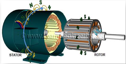
Both synchronous and induction machines work on AC supply, ie; they are AC machines. For AC machines, the basic requirement is to create a rotational magnetic field so that the rotor can rotate, and energy can be obtained. (mechanical for motor, electrical for alternator) Now, the difference between a synchronous machine and an induction machine is based on how the rotational magnetic field is utilized.

The three phase supply, when given to the stator windings, creates a rotating magnetic field. Now, the rotor of an induction machine is a group of short circuited windings where the rotating magnetic field is to act. The underlying principle is electromagnetic induction, similar to transformers – the rotor gets an induced current, that means – a current carrying loop inside the magnetic field. This makes the rotor rotate. But, if both rotating magnetic field and rotor rotate in the same synchronous speed, there will be no induced EMF inside the rotor, because the field will be then constant w.r.t the rotor, and for rotation, change in flux should be there.

Thus, the rotation happens with a “slip” between the rotor and the stator. The slip refers to the inability of the rotor to catch up with the (speed of) rotating stator magnetic field. Thus rotor will rotate, and output is obtained, if there is slip between the rotor and stator magnetic field. This is the principle of working of an induction machine.

Now, consider am utilizing the rotating magnetic field by making an electromagnet rotate as a rotor, which is fed with a DC supply. In such a case, the machine will run in synchronous speed, and this machine is called a synchronous machine. However, it is to be noted that due to inertia of the rotor, the rotor electromagnet cannot immediately respond to the rotating magnetic field. This means that the synchronous machine does not start by itself. To provide the starting torque, additional winding called “damper winding” is provided in rotor, which make the synchronous machine similar to an induction machine during starting. As the machine starts, the rotor naturally locks up with the rotating magnetic field and rotates in synchronous speed. This means that during normal running conditions, the damper winding will carry no current. (Similar to the rotor winding in an induction machine at synchronous speed)

Differences:

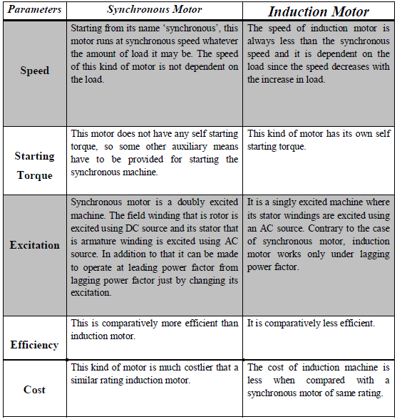
Here are the few Differences between Synchronous and Induction Motor


post

Synchronous Motor and Methods of Starting a Synchronous Motors

Electrical motor in general is an electro-mechanical device that converts energy from electrical domain to  mechanical domain. Based on the type of input we have classified it into single phase and 3 phase motors. Among 3 phase motors, induction motors and synchronous motors are more widely used. When a 3 phase electric conductors are placed in a certain geometrical positions (In certain angle from one another) then an electrical field is generated. Now the rotating magnetic field rotates at a certain speed, that speed is called synchronous speed. Now if an electromagnet is present in this rotating magnetic field, the electromagnet is magnetically locked with this rotating magnetic field and rotates with same speed of rotating field. Synchronous motors is called so because the speed of the rotor of this motor is same as the rotating magnetic field. It is basically a fixed speed motor because it has only one speed, which is synchronous speed and therefore no intermediate speed is there or in other words it’s in synchronism with the supply frequency.

Why is a synchronous motor not self starting?

At starting position of synchronous machine, the rotor could have any alternative position as shown here.

When rotor is initially at position (a):

The like pole of rotor will get repelled and the tendency of rotor will be to rotate in anticlockwise direction. But after some time the N-pole of rotor and S-pole of rotor comes face to face and will try to get attract with each other. Now, the tendency of rotor is to rotate in clockwise direction but the rotor have some mass and cannot attain such a high speed (synchronous speed) to that of stator’s rotating magnetic field. Hence, rotor remains at rest.

When rotor is initially at position (b):

Here, the unlike pole of rotor gets attracted but as explained earlier the rotor cannot attain synchronous speed immediately and remains at rest.

As a result, the average torque exerted on the rotor is zero. Due to the large inertia of the rotor, the rotor fails to rotate along with the stator poles. Hence again the difference of position of magnetic axis gets created and rotor gets subjected to quickly reversing torque. This is because the speed with which rotating magnetic field is rotating is so high that it is unable to rotate the rotor from its initial position, due to the inertia of the rotor. So under any case, whatever may be the starting position of the rotor, synchronous motor is not self starting.

Methods of Starting a Synchronous Motor

The synchronous machine, however, is not self-starting. The synchronous machine has to be rotated to near the synchronous speed of the stator before it can “catch” the stator field and begin rotating on its own. Basically there are three methods that are used to start a synchronous motor:

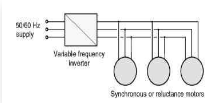
To reduce the speed of the rotating magnetic field of the stator to a low enough value that the rotor can easily accelerate and lock in with it during one half-cycle of the rotating magnetic field’s rotation. This is done by reducing the frequency of the applied electric power. This method is usually followed in the case of inverter-fed synchronous motor operating under variable speed drive applications.To use an external prime mover to accelerate the rotor of synchronous motor near to its synchronous speed and then supply the rotor as well as stator. Of course care should be taken to ensure that the direction of rotation of the rotor as well as that of the rotating magnetic field of the stator are the same. This method is usually followed in the laboratory- the synchronous machine is started as a generator and is then connected to the supply mains by following the synchronization or paralleling procedure. Then the power supply to the prime mover is disconnected so that the synchronous machine will continue to operate as a motor.To use damper windings or amortisseur windings if these are provided in the machine. The damper windings or amortisseur windings are provided in most of the large synchronous motors in order to nullify the oscillations of the rotor whenever the synchronous machine is subjected to a periodically varying load.

Each of these methods of starting a synchronous motor is described below in detail.

1. Motor Starting by Reducing the supply Frequency:

If the rotating magnetic field of the stator in a synchronous motor rotates at a low enough speed, there will be no problem for the rotor to accelerate and to lock in with the stator’s magnetic field.The speed of the stator magnetic field can then be increased to its rated operating speed by gradually increasing the supply frequency f up to its normal 50- or 60-Hz value. This approach to starting of synchronous motors makes a lot of sense, but there is a big problem: Where from can we get the variable frequency supply? The usual power supply systems generally regulate the frequency to be 50 or 60 Hz as the case may be. However, variable-frequency voltage source can be obtained from a dedicated generator only in the olden days and such a situation was obviously impractical except for very unusual or special drive applications.

Synchronous Motor


But the present day solid state power converters offer an easy solution to this. We now have the rectifier- inverter and cyclo-converters, which can be used to convert a constant frequency AC supply to a variable frequency AC supply. With the development of such modern solid-state variable-frequency drive packages, it is thus possible to continuously control the frequency of the supply connected to the synchronous motor all the way from a fraction of a hertz up to and even above the normal rated frequency. If such a variable frequency drive unit is included in a motor-control circuit to achieve speed control, then starting the synchronous motor is very easy-simply adjust the frequency to a very low value for starting, and then raise it up to the desired operating frequency for normal running.

When a synchronous motor is operated at a speed lower than the rated speed, its internal generated voltage (usually called the counter EMF) EA = K_! will be smaller than normal. As such the terminal voltage applied to the motor must be reduced proportionally with the frequency in order to keep the stator current within the rated value. Generally, the voltage in any variable-frequency power supply varies roughly linearly with the output frequency.

2. Motor Starting with an External Motor:

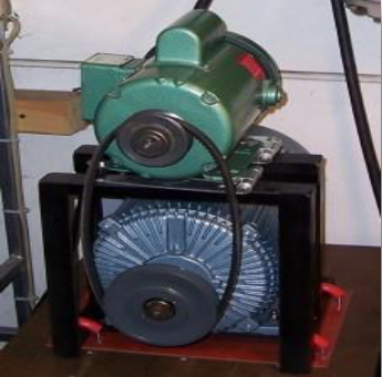
The second method of starting a synchronous motor is to attach an external starting motor (pony motor) to it and bring the synchronous machine to near about its rated speed (but not exactly equal to it, as the synchronization process may fail to indicate the point of closure of the main switch connecting the synchronous machine to the supply system) with the pony motor. Then the output of the synchronous machine can be synchronized or paralleled with its power supply system as a generator, and the pony motor can be detached from the shaft of the machine or the supply to the pony motor can be disconnected. Once the pony motor is turned OFF, the shaft of the machine slows down, the speed of the rotor magnetic fieldBR falls behind Bnet, momentarily and the synchronous machine continues to operate as a motor. As soon as it begins to operate as a motor the synchronous motor can be loaded in the usual manner just like any motor.

Synchronous Motor


This whole procedure is not as cumbersome as it sounds, since many synchronous motors are parts of motor-generator sets, and the synchronous machine in the motor-generator set may be started with the other machine serving as the starting motor. Moreover, the starting motor is required to overcome only the mechanical inertia of the synchronous machine without any mechanical load (load is attached only after the synchronous machine is paralleled to the power supply system). Since only the motor’s inertia must be overcome, the starting motor can have a much smaller rating than the synchronous motor it is going to start. Generally most of the large synchronous motors have brushless excitation systems mounted on their shafts. It is then possible to use these exciters as the starting motors. For many medium-size to large synchronous motors, an external starting motor or starting by using the exciter may be the only possible solution, because the power systems they are tied to may not be able to handle the starting currents needed to use the damper (amortisseur) winding approach described next.

3. Motor Starting by Using damper (Amortisseur) Winding:

As already mentioned earlier most of the large synchronous motors are provided with damper windings, in order to nullify the oscillations of the rotor whenever the synchronous machine is subjected to a periodically varying load. Damper windings are special bars laid into slots cut in the pole face of a synchronous machine and then shorted out on each end by a large shorting ring, similar to the squirrel cage rotor bars. A pole face with a set of damper windings is shown in Figure.

Synchronous Motor


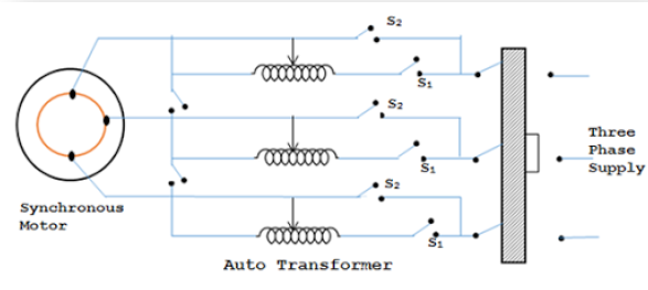
When the stator of such a synchronous machine is connected to the 3-Phase AC supply, the machine starts as a 3-Phase induction machine due to the presence of the damper bars, just like a squirrel cage induction motor. Just as in the case of a 3-Phase squirrel cage induction motor, the applied voltage must be suitably reduced so as to limit the starting current to the safe rated value. Once the motor picks up to a speed near about its synchronous speed, the DC supply to its field winding is connected and the synchronous motor pulls into step i.e. it continues to operate as a Synchronous motor running at its synchronous speed.

post

What is Synchronous Machine and Its Basic Working Principle

Synchronous Machine

Electrical motor in general is an electro-mechanical device that converts energy from electrical domain to mechanical domain. Based on the type of input we have classified it into single phase and 3 phase motors. Among 3 phase motors, induction motors and synchronous machine are more widely used. When a 3 phase electric conductors are placed in a certain geometrical positions (In certain angle from one another) then an electrical field is generated. Now the rotating magnetic field rotates at a certain speed, that speed is called synchronous speed. Now if an electromagnet is present in this rotating magnetic field, the electromagnet is magnetically locked with this rotating magnetic field and rotates with same speed of rotating field. Synchronous motors is called so because the speed of the rotor of this motor is same as the rotating magnetic field. It is basically a fixed speed motor because it has only one speed, which is synchronous speed and therefore no intermediate speed is there or in other words it’s in synchronism with the supply frequency.

Synchronous motors are available in self-excited sub-fractional horsepower sizes to high power industrial sizes.In the fractional horsepower range, most synchronous motors are used where precise constant speed is required. These machines are commonly used in analog electric clocks, timers and other devices where correct time is required. In higher power industrial sizes, the synchronous motor provides two important functions. First, it is a highly efficient means of converting AC energy to work. Second, it can operate at leading or unity power factor and thereby provide power-factor correction.

Synchronous speed:


The synchronous speed of a synchronous motor is given:

in rpm, by:


and in rad·s−1, by:


where:


 is the frequency of the AC supply current in Hz,

 is the number of poles per phase.

 is the pair number of poles per phase. 


/2

If 

 is the number of pole pairs per phase (rarely, planes of commutation) instead, simply divide both formulas by 2.

where f = supply frequency & p = no. of poles

Synchronous Machine


Synchronous motor is a doubly excited machine i.e two electrical inputs are provided to it. It’s stator winding which consists of a 3 phase winding is provided with 3 phase supply and rotor is provided with DC supply. The 3 phase stator winding carrying 3 phase currents produces 3 phase rotating magnetic flux. The rotor carrying DC supply also produces a constant flux.


Did you miss our previous article…
https://countryelectric.biz/?p=106

post

Chargepoint Home Flex EV Charger Installation Services

Electricians Review of the Chargepoint Home Flex

In the past few months, Root Electric has had quite a few requests to install wall connectors for newly purchased electric vehicles.  As more and more manufacturers are beginning to release electric vehicles, the demand for home charging solutions that will work with a variety of different vehicles is on the rise.  One new product of note is the ChargePoint Home Flex wall connector.  There are many technological features, such as the ChargePoint app that are easily understood from the standpoint of the average consumer.  However, since I am a professional electrician, I would like to review this product based on my knowledge and experience as an electrician.

The ChargePoint Home Flex is designed specifically so that the user can select the amount of electrical current drawn to charge the vehicle.  The range of current draw options for the ChargePoint Home Flex range from 16 Amps, all the way up to 50 Amps.  You may be reading this review thinking, “Well why would I want to set up the wall connector to charge my car at 16 Amps, when I can just set it to 50 Amps?” Well, that’s the correct question to ask, because it has the largest effect on the potential installation costs and future upgradeability of the installation.  I am going to delve into some of the more technical aspects of home EV charging for the benefit of the serious EV enthusiast.  Likewise, if you are an engineer reading this article, you may find that some of the more technical aspects are, let’s say, “general” for the sake of the less technically inclined. So if your mind begins to wander, or if the numbers aren’t tight to the NEC tables, please bear with me.  

One of the largest hindrances to installation of a home charging option for electric vehicles is the size of the electrical service on most homes in the United States.  Most homes in American suburbia are in the range of 50 years old or greater.  Most of these older homes have electrical services that range in size from 60 Amps to 150 Amps, while newer homes in most areas have a minimum service size of 200 Amps or greater.  The reason for this gradual increase in the size of home electrical services is the rise in reliance on electricity for cooking, refrigeration, heating, and cooling. In the mid 20th Century, most homes used fuel oil or natural gas for heat and cooking, but since the 1970’s, electricity has come to play a larger role especially because of the increased popularity of central heating and air conditioning.  Industry research has shown that the HVAC system in your home accounts for at least 30% of its energy consumption.  That said, many older homes that originally did not have air conditioning have since been upgraded to feature central air conditioning.  The rub is that while the HVAC system was upgraded, more often than not, the electrical service was left at its original size, which was not designed for the additional load of the air conditioning.  This leaves many older homes with an already maxed-out or overloaded electrical service that technically cannot handle additional load.  To make matters worse, many new homes are built with an electrical service that is pushed to its max.  So while the service may be rated at 200 amps, there may be precious little room for electrical upgrades. 

Customer Testimonial


Exemplary electrical work and customer service. This is the second time I have used Root Electric and they will continue to be my “go to” electrical contractor. The on-line estimate quote process works very well – there were no surprises. Bill Sr. gave me a 10:00 – 12:00 service window; he called at 10:00 to say he would arrive in 30 – 45 minutes. Bill wore a protective mask at all times, was very respectful and aware of social distancing. The two jobs were completed quickly. All in all, a real pleasure to work with.

Bruce G.


So what does this have to do with the installation with an electric vehicle?  Well it comes down to the amount of electrical current that a wall connector such as the ChargePoint Home Flex can pull.  At it’s full 50 Amp setting, the wall connector pulls as much electricity as your average kitchen electric range.  However, unlike your range, which is generally only being partially used (for example, you may only use one of the burners at once, or the oven itself without the cooktop), the EV charger is pulling its maximum current for hours at a time.  Because of this, electricians have to calculate the load placed on the electrical system to allow for the extended time high-current draw of the electric vehicle wall connector.  As an example, for standard residential electrical load calculations, your 50 amp range may only be calculated in at somewhere around 50% of its full load.  For easy math, that means if you have a 50 amp range, only 25 amps will be calculated into the total load placed on your electrical service.  This is because you are not using your range all of the time, and when you are, you are likely only using a fraction of its potential electricity draw.  A power connector for an electric vehicle, on the other hand, has to be calculated at 125% of its total draw.  This means that if you have a power connector rated at 40 Amps, you have to enter 50 amps to calculate the draw on the service.  If you have a newer home with gas heat and a 200 amp service, this won’t be a problem, but if your house was built in the 1950’s and has the original 60 amp service, and a central air conditioner installed in the late 1970’s, along with a remodeled kitchen, the service may not be able to support the load of the power connector without having to be upgraded.  This means additional expense on top of what you just spent on the car and on having the circuit and power connector installed.  (Although, if you have an older house, upgrading the service is a very good idea both for the long term safety and value of the home.)  

So where does all of this electrical mumbo-jumbo come in to play when it comes to the ChargePoint Home Flex?  Well, let’s say you just signed the lease on a shiny new Audi e-Tron and had Amazon deliver a new power connector to your doorstep.  Then you call an electrician to give you an estimate for installing a new 50 amp circuit, plus mount the new wall connector.  When he tells you that your service is not heavy enough to support the 50 amp load, you still have options to set the wall connector to 32 amps, 24 amps, or even 16 amps, and still have the option to increase the load to the full 50 amps in the future if you upgrade the service.  (Assuming the conductors feeding the power connector are large enough to support a 50 amp wall connector). 

Another advantage to having the option to pick the wall connector’s current draw is that you can choose how you want the wall connector to connect to your electrical system.  If you want maximum current draw at 48 or 50 amps for the fastest charge time, you can opt to have the ChargePoint Home Flex hardwired.  However, if you are willing to sacrifice a little bit of charging speed (limiting you to 40 amps or below) for the sake of being able to install more advanced power connectors in the future, you can have your electrician install a NEMA 14-50R or 6-50R outlet, which will work with just about every EV mobile connector or wall connector.  If you plan to sell your house in the near future, installing a 14-50R outlet or 6-50R outlet is a smart choice, since it will let the next homeowner install a power connector of their choice to power their own electric vehicle, which adds value to your home at the time of sale.  

If your head isn’t spinning by now, hopefully you now have a better grasp of the technical reasons of why the ChargePoint Home Flex is an excellent choice for a home EV charging power connector.  If you have an older home with a small electrical service, or even a newer home with a heavily loaded service, the ChargePoint Home Flex will give you options to safely charge your electric vehicle.  Additionally, it grants you the flexibility to set it up for fastest charging time or maximum future flexibility and upgradability.  There are many power connectors on the market, and while I am not in any way endorsing or promoting the ChargePoint Home Flex, I am saying that it would be worth a look for your electric vehicle charging needs.  

REQUEST A FREE QUOTE

Satisfaction / Safety First Since 1986

Contact Now!lorem ipsum dolor

More Articles About Home Electrical Improvement

faq-electrical-vehicles

FAQs About Electric Vehicles

Read More

electrical-inspection-contractor

Electrical Home Safety Inspections

Read More

Connections for Electric Vehicles

EV Charging Station Installation Service

Read More