post

Bollard Lights For Exterior Landscape Lighting

Residential>Troubleshooting & Repair ServicesGFCI OutletsAFCI BreakersWhole House Surge ProtectionElectrical Safety InspectionsSmoke & CO DetectorsGenerator InstallationElectrical Panel UpgradesDedicated CircuitsIndoor LightingLandscape LightingFan InstallationPool & Hot Tub WiringEV Charger InstallationWhole House RewiringHome Theater InstallationCommercial>Troubleshooting & Repair ServicesDedicated Computer CircuitsElectrical Safety InspectionsSurge ProtectionGenerator InstallationElectrical Panel UpgradesBucket Truck ServicesEquipment HookupsIndoor & Outdoor LightingReviewsService Areas>Montgomery County, PABucks County, PAChester County, PADelaware County, PABerks County, PAPhiladelphia County, PAPhotosTeamBlogDealsCommunityAchievementsComicsCareersCompanies

Bollard Lights For Exterior Landscape Lighting

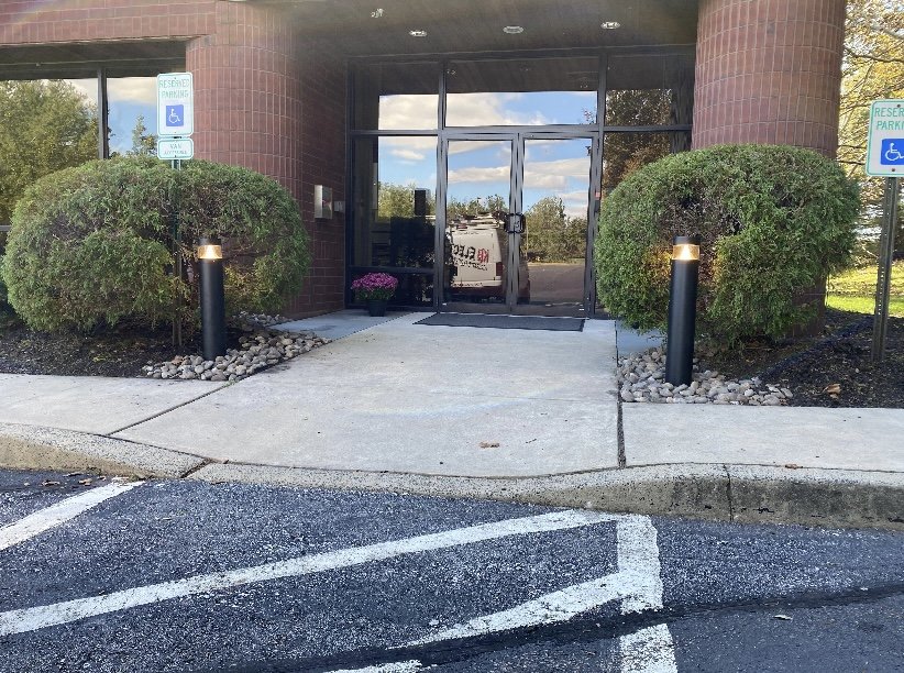
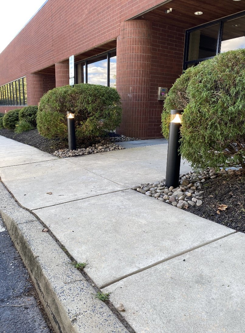
KB Electric LLC just finished an awesome job for a commercial property involving bollard lights. So today we are going to blog all about bollard lights, their usefulness, and who to call for installation.


What Are Bollard Lights?

A bollard light fixture is a type of fixture that is used for exterior landscape lighting that is ground-mounted. As pictured below, the light fixture is on a bollard, which is a short vertical post. Bollard lighting comes in various types and styles for individual preference. You’ll most likely see a bollard light on commercial properties along pathways and at the front of building entrances. These fixtures can also be used for residential landscape lighting as well. 

As with many other types of residential and commercial light fixtures, bollard lighting can either have LED, halogen, incandescent, metal halide, or fluorescent bulbs; however, the majority you will find now are of the LED type. LEDs are more energy efficient than their counterparts, and we recommend going with this option for efficiency, longevity of the bulb, and savings.


Bollard Light Installation


Uses Of Bollard Lights

Bollard light fixtures can be used to:

Illuminate PathwaysHighlight Trees, Gardens, and ShrubberyIlluminate DrivewaysIlluminate Parking LotsIlluminate Building Entrances


bollard lights
bollard lights


Types Of Bollard Lights 

Line Voltage

This type of bollard lighting uses line voltage, or 120v, similar to your standard home outlets. 

Low Voltage

This type of bollard light uses low voltage and a transformer to step the voltage down from 120v to 12/24v.
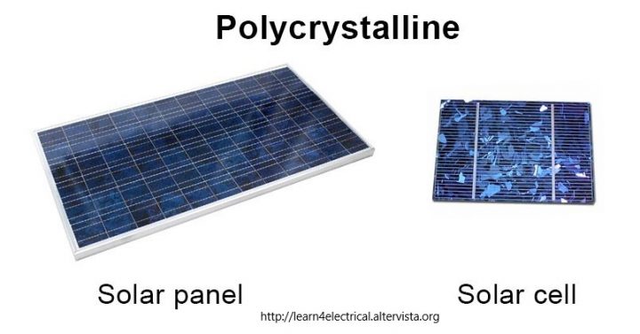
Solar 

Using the power of the sun, solar bollard lights are powered by sunlight.


bollard light installation


Styles of Bollard Light Fixtures

There are many different styles and shapes of bollard light fixtures. The main designs you will find online on Home Depot’s website have a rounded dome top, square top, or a circular flat top. A wide variety to match any type of property, these exterior lighting fixtures come in many finishes such as stainless steel, bronze, amber, black, aluminum etc. 


Hire A Licensed Electrician For Bollard Light Installation

The master electricians at KB Electric LLC can install any and all types of bollard light fixtures for your commercial or residential property. We can recommend the best type, and the specific amount of bollard lights needed for any exterior landscape area. Our licensed and insured electricians have the field experience and NEC (National Electrical Code) knowledge to install them safely and properly. Call us today for all of your bollard light installation needs! (267) 467-3178


CATEGORIES

4-Prong OutletsAbout KB Electric LLCAttic FansBallast ReplacementBathroom LightingBollard LightsCable Outlet InstallationCarbon Monoxide DetectorsCeiling Fan InstallationChandelier InstallationChristmas Light SafetyCircuit BreakersCommercial Electrical Safety InspectionsCommercial ElectricianCommercial LightingCurrent Events with ElectricityCurrent Events: EnergyDeck LightingDeck Receptacles/OutletsDedicated CircuitsDeicing CablesDimmer SwitchesDisposing Light BulbsDoorbellsDryer Booster FansElectricity and Energy InnovationsElectric Baseboard Heater InstallationElectric Car Charging InstallationElectric Radiant Floor HeatingElectrical InformationElectrical InnovationsElectrical Panel UpgradeElectrical Remodeling ServicesElectrical Safety InspectionsElectrician vs. Electrical InspectorElectricity BillElectromagnetic FieldsEmergency DisconnectsEmergency Lighting and Exit Sign LightingEnergy Saving TipsEthernet Wall JacksEV Charging SafetyExhaust FansFestoon LightingGarage WiringGeneratorsGFCIsHigh Bay LightingHire a Licensed ElectricianHistory of Ceiling FansHistory of the Dimmer SwitchHistory of Electric CarsHome Electric Car Charging InstallationHot Tub WiringHouse RewireIn The NewsIntercom SystemsKitchen LightingKnob & Tube WiringLED Ballast BypassLED Christmas LightsLED Retrofit LightingLEDsLi-Fi TechnologyLight Color TemperatureLightingLightning FactsLow Voltage Landscape LightingMotion SensorsMoonlightingOutlet SafetyOutdoor Ceiling FansOutdoor Home Security Lighting TipsOutdoor Lamp PostsOutdoor LightingOutdoor Outlet CoversOutdoor Receptacles/OutletsOutdoor Shed WiringParking Lot LightingPendant LightingPhotocell SensorsPool WiringPower and Communication PolesProperty Management ElectricianRange HoodsRecessed LightsRecessed OutletsRenewable EnergyRomex WiringRV Home Electrical HookupSafety & PreventionShed WiringSingle Phase to Three PhaseSmall BusinessesSmart Light SwitchesSmart OutletsSmart ThermostatsSmoke DetectorsSolar Powered ElectricitySpace HeatersStorefront LightingSurge ProtectionSwimming Pool Electrical SafetySwimming Pool Area LightingSwimming Pool LightingThanksgiving FunTools of the TradeTrack Lighting InstallationTransformersTunable White LEDsTV Wall Mount InstallationTwist Lock ReceptaclesUnder Cabinet LightingUSB OutletsVideo Doorbells

The post Bollard Lights For Exterior Landscape Lighting appeared first on KB Electric LLC.

Did you miss our previous article…
https://countryelectric.biz/?p=204

post

Occupancy Sensors: What They Are And Who To Hire For Installation

Residential>Troubleshooting & Repair ServicesGFCI OutletsAFCI BreakersWhole House Surge ProtectionElectrical Safety InspectionsSmoke & CO DetectorsGenerator InstallationElectrical Panel UpgradesDedicated CircuitsIndoor LightingLandscape LightingFan InstallationPool & Hot Tub WiringEV Charger InstallationWhole House RewiringHome Theater InstallationCommercial>Troubleshooting & Repair ServicesDedicated Computer CircuitsElectrical Safety InspectionsSurge ProtectionGenerator InstallationElectrical Panel UpgradesBucket Truck ServicesEquipment HookupsIndoor & Outdoor LightingReviewsService Areas>Montgomery County, PABucks County, PAChester County, PADelaware County, PABerks County, PAPhiladelphia County, PAPhotosTeamBlogDealsCommunityAchievementsComicsCareersCompanies

Occupancy Sensors: What They Are And Who To Hire For Installation

You’ll most often see occupancy sensors installed in a commercial setting like in an office building. In other instances, a person may use occupancy sensors for personal use for their residential property. Whether for a business or a home, an occupancy sensor installation is best done by a licensed and insured professional like the master electricians at KB Electric LLC. Let’s go over what an occupancy sensor is, why it’s best to hire an electrician, and why you might want this device for your business or home setting.


Occupancy Sensor Installation for Residential Garage Lighting


What Is An Occupancy Sensor?

An occupancy sensor is a device that detects when a person enters a room or area. When a person enters a room, the occupancy sensor will turn lights ON automatically. The lights in a room will then turn OFF when a person has left a room and a preset time has gone by. Occupancy sensors can also control other things besides lighting like heating and cooling systems.


Difference Between An Occupancy Sensor And A “Motion Sensor”

An occupancy sensor is considered a type of a motion sensor, but not the one you might think of that hangs above your garage on your floodlight. Most motion sensors that are on a residential flood light have what is called a photocell, which works at nighttime by detecting the dark. Also, while both an occupancy sensor and a motion sensor detect movement of a person, an occupancy sensor is designed to detect subtle motions of people in a room/area AND when a person is stationary. Motion sensors are thus more sensitive than occupancy sensors to moving objects, picking up on mostly clear walking motions. 


How Do Occupancy Sensors Work?

There are many types of occupancy sensors based on different technologies. All detect movement of a person in a room/area. There are three main types used today:

Passive Infrared (PIR)Ultrasonic SensorsDual Technology (Both PIR and Ultrasonic) 

PIR occupancy sensors use a person’s body temperature to detect when someone is in a room. 

Ultrasonic sensors for an occupancy sensor use sound waves that have a very high frequency. When the sound wave frequency changes by the presence of a person in a room, the lights on this type of occupancy sensor will then turn on.

Dual technology occupancy sensors use both PIR and ultrasonic technology to detect the motion of a person in an area. These devices with both technologies working in conjunction with each other eliminates room for error. Pairing these two technologies creates a seamless way for automatic control for lighting and heating/cooling systems. You want to use these two together in certain environments where people aren’t moving as much, but are still present in the area/room, like a lecture hall.


Best Places To Install An Occupancy Sensor

ClassroomsConference roomsOpen office areas (large space with cubicles)Small office roomsHallwaysWarehousesBathroomsGymsCommercial/Residential GaragesUtility ClosetsCafeterias/Lunchrooms 

Benefits of Occupancy Sensors For Your Business

Save on energy costs for lighting, heating, cooling, or all three.Automatic control option.Never forget to turn off the lights.Helps meet building code requirements. 

Who To Call For Occupancy Sensor Installation

Hire a licensed and insured electrician for occupancy sensor installation. The electricians at KB Electric LLC can help with:

Placement of your occupancy sensors.Wiring of your occupancy sensors.Choosing the right type of occupancy sensor for your specific need.Ensuring smooth installation up to NEC standards. 

KB Electric LLC can install occupancy sensors in and around the Montgomery County, PA area. Our main office is located in Pottstown, PA, but we serve all of the surrounding Southeastern, PA counties of Berks, Bucks, Delaware, and Chester counties. Call us today for a consultation for occupancy sensor installation services for your commercial property or residential property! (267) 467-3178

CATEGORIES

4-Prong OutletsAbout KB Electric LLCAttic FansBallast ReplacementBathroom LightingBollard LightsCable Outlet InstallationCarbon Monoxide DetectorsCeiling Fan InstallationChandelier InstallationChristmas Light SafetyCircuit BreakersCommercial Electrical Safety InspectionsCommercial ElectricianCommercial LightingCurrent Events with ElectricityCurrent Events: EnergyDeck LightingDeck Receptacles/OutletsDedicated CircuitsDeicing CablesDimmer SwitchesDisposing Light BulbsDoorbellsDryer Booster FansElectricity and Energy InnovationsElectric Baseboard Heater InstallationElectric Car Charging InstallationElectric Radiant Floor HeatingElectrical InformationElectrical InnovationsElectrical Panel UpgradeElectrical Remodeling ServicesElectrical Safety InspectionsElectrician vs. Electrical InspectorElectricity BillElectromagnetic FieldsEmergency DisconnectsEmergency Lighting and Exit Sign LightingEnergy Saving TipsEthernet Wall JacksEV Charging SafetyExhaust FansFestoon LightingGarage WiringGeneratorsGFCIsHigh Bay LightingHire a Licensed ElectricianHistory of Ceiling FansHistory of the Dimmer SwitchHistory of Electric CarsHome Electric Car Charging InstallationHot Tub WiringHouse RewireIn The NewsIntercom SystemsKitchen LightingKnob & Tube WiringLED Ballast BypassLED Christmas LightsLED Retrofit LightingLEDsLi-Fi TechnologyLight Color TemperatureLightingLightning FactsLow Voltage Landscape LightingMotion SensorsMoonlightingOutlet SafetyOutdoor Ceiling FansOutdoor Home Security Lighting TipsOutdoor Lamp PostsOutdoor LightingOutdoor Outlet CoversOutdoor Receptacles/OutletsOutdoor Shed WiringParking Lot LightingPendant LightingPhotocell SensorsPool WiringPower and Communication PolesProperty Management ElectricianRange HoodsRecessed LightsRecessed OutletsRenewable EnergyRomex WiringRV Home Electrical HookupSafety & PreventionShed WiringSingle Phase to Three PhaseSmall BusinessesSmart Light SwitchesSmart OutletsSmart ThermostatsSmoke DetectorsSolar Powered ElectricitySpace HeatersStorefront LightingSurge ProtectionSwimming Pool Electrical SafetySwimming Pool Area LightingSwimming Pool LightingThanksgiving FunTools of the TradeTrack Lighting InstallationTransformersTunable White LEDsTV Wall Mount InstallationTwist Lock ReceptaclesUnder Cabinet LightingUSB OutletsVideo Doorbells

The post Occupancy Sensors: What They Are And Who To Hire For Installation appeared first on KB Electric LLC.

Did you miss our previous article…
https://countryelectric.biz/?p=198

post

Circuit Breaker And Types of Low Voltage Circuit Breakers

A circuit breaker is an equipment which can open or close a circuit under all conditions viz. no load, full load and fault conditions. It is so designed that it can be operated manually (or by remote control) under normal conditions and automatically under fault conditions. For the latter operation, a relay circuit is used with a circuit breaker.

Types of Low Voltage Circuit Breakers


1. Miniature Circuit Breaker

A miniature circuit breaker (MCB) automatically switches off electrical circuit during an abnormal condition of the network means in overload condition as well as faulty condition. Nowadays we use an MCB in low voltage electrical network instead of a fuse. The fuse may not sense it but the miniature circuit breaker does it in a more reliable way. MCB is much more sensitive to over-current than fuse. Handling an MCB is electrically safer than a fuse. Quick restoration of supply is possible in case of a fuse as because fuses must be re-wirable or replaced for restoring the supply. Restoration is easily possible by just switching it ON.

• The working principle of MCB

Whenever continuous over-current flows through MCB, the bimetallic strip is heated and deflects by bending. This deflection of bimetallic strip releases a mechanical latch. As this mechanical latch is attached with the operating mechanism, it causes to open the miniature circuit breaker contacts, and the MCB turns off thereby stopping the current to flow in the circuit. To restart the flow of current the MCB must be manually turned ON. This mechanism protects from the faults arising due to over-current or overload.

But during short circuit condition, the current rises suddenly, causing electromechanical displacement of plunger associated with a tripping coil or solenoid. The plunger strikes the trip lever causing immediate release of latch mechanism consequently open the circuit breaker contacts. This was a simple explanation of a miniature circuit breaker working principle.

An MCB is very simple, easy to use and is not generally repaired. It is just easier to replace. The trip unit is the main part, responsible for its proper working. There are two main types of trip mechanism. A bi-metal provides protection against overload current and an electromagnet provides protection against short-circuit current.

• Advantages of MCBs over Fuse

Easily identify the faulty zone of an electrical circuitSimple to resume supplyBetter interface: KnobElectrically saferMore sensitive to current than the fuseLess maintenance and replacement cost.

• Disadvantages of MCBs

✓ Only disadvantage over fuse is, this device is costly

2. Moulded Case Circuit Breaker

Molded case circuit breakers are a type of electrical protection device that is commonly used when load currents exceed the capabilities of miniature circuit breakers. They are also used in applications of any current rating that require adjustable trip settings, which are not available in plug-in circuit breakers and MCBs.

Circuit Breaker

The traditional molded-case circuit breaker uses electromechanical (thermal magnetic) trip units that may be fixed or interchangeable. An MCCB provides protection by combining a temperature sensitive device with a current sensitive electromagnetic device. Both these devices act mechanically on the trip mechanism.

As with most types of circuit breakers, an MCCB has three main functions:

• Protection against overload – currents above the rated value that last longer than what is normal for the application.

• Against electrical faults – During a fault such as a short circuit or line fault, there are extremely high currents that must be interrupted immediately.

• Switching a circuit on and off – This is a less common function of circuit breakers, but they can be used for that purpose if there isn’t an adequate manual switch.

• Molded Case Circuit Breaker Operating Mechanism

At its core, the protection mechanism employed by MCCBs is based on the same physical principles used by all types of thermal-magnetic circuit breakers.

Overload protection is accomplished by means of a thermal mechanism. MCCBs have a bimetallic contact what expands and contracts in response to changes in temperature. Under normal operating conditions, the contact allows electric current through the MCCB. However, as soon as the current exceeds the adjusted trip value, the contact will start to heat and expand until the circuit is interrupted. The thermal protection against overload is designed with a time delay to allow short duration over-current, which is a normal part of operation for many devices. However, any over-current conditions that last more than what is normally expected represent an overload, and the MCCB is tripped to protect the equipment and personnel.

On the other hand, fault protection is accomplished with electromagnetic induction, and the response is instant. Fault currents should be interrupted immediately, no matter if their duration is short or long. Whenever a fault occurs, the extremely high current induces a magnetic field in a solenoid coil located inside the breaker – this magnetic induction trips a contact and current is interrupted. As a complement to the magnetic protection mechanism, MCCBs have internal arc dissipation measures to facilitate interruption.

As with all types of circuit breakers, the MCCB includes a disconnection switch which is used to trip the breaker manually. It is used whenever the electric supply must be disconnected to carry out field work such as maintenance or equipment upgrades.

• Advantages of MCCBs

Prevents the electrical devices from faulty situation.MCCBs are compact in size and hence saves a wide space in the panel design.It takes less time to reset and to switch on while it trips down during the faults.Its maintenance fee is free and at times costs less.Along with the MCCBs, there are certain accessories which can be fitted and few also act as multi-purpose usage.

3. Residual Current Circuit Breaker

The Residual Current Circuit breaker RCCBs are the safest device to detect and trip against electrical leakage currents, thus ensuring protection against electric shock caused by indirect contacts. These devices must be used in series with an MCB or fuse which protects them from the potentially damaging thermal and dynamic stresses of any over currents. They also act as the main disconnecting switches upstream of any derived MCBs (e.g. domestic consumer unit).

Its working based on Kirchhoff’s Current Law i.e. the incoming current in a circuit must be equal to the outgoing current from that circuit. This circuit breaker is made such that whenever a fault occurs the current balance of line and neutral did not matches (imbalance occurs). Its circuit is made such that every instance it compares the value of incoming and outgoing circuit current. Whenever it is not equal, the residual current which is basically the difference between the two currents actuates the circuit to trip/switch off.

Working Principle of Residual Current Circuit Breaker

The basic operating principle lies in the Toroidal Transformer shown in the diagram containing three coils. There are two coils say Primary (containing line current) and Secondary (containing neutral current) which produces equal and opposite fluxes if both currents are equal. Whenever in the case there is a fault and both the currents changes, it creates out of balance flux, which in-turn produces the differential current which flows through the third coil (sensing coil shown in the figure) which is connected to relay. The Toroidal transformer, sensing coil and relay together is known as RCD – Residual Current Device.

Circuit Breaker

Test Circuit:

The test circuit is always included with the RCD which basically connects between the line conductor on the load side and the supply neutral. It helps to test the circuit when it is on or off the live supply. Whenever the test button is pushed current starts flowing through the test circuit depending upon the resistance provided in this circuit. This current passes through the RCD line side coil along with load current. But as this circuit bypasses neutral side coil of RCD, there will be an unbalance between the line side and neutral side coil of the device and consequently, the RCCB trips to disconnect the supply even in normal condition. This is how the test circuit tests the reliability of RCCB.

post

Main Equipment of Switch Gear and Their Working

Equipment of Switch Gear

Following are the main Equipment of Switch Gear,

1) Switches

A switch is main equipment of switch gear, it is a device which is used to open or close an electrical circuit in a convenient way. It can be used under full-load or no-load conditions but it cannot interrupt the fault currents. When the contacts of a switch are opened, an arc is produced in the air between the contacts. This is particularly true for circuits of high voltage and large current capacity.
The switches may be classified into:

a) Disconnector (or isolator)

This switch is a manually-operated, lockable, two-position device (open/closed) which provides safe isolation of a circuit when locked in the open position. Its characteristics are defined in IEC 60947-3. A disconnector is not designed to make or to break current and no rated values for these functions are given in standards. It must, however, be capable of withstanding the passage of short-circuit currents and is assigned a rated short-time withstand capability, generally for 1 second, unless otherwise agreed between user and manufacturer. This capability is normally more than adequate for longer periods of (lower-valued) operational over current, such as those of motor-starting. Standardized mechanical-endurance, over voltage, and leakage-current tests, must also be satisfied.

b) Load-breaking switch

This control switch is generally operated manually (but is sometimes provided with electrical tripping for operator convenience) and is a non-automatic two-position device (open/closed). It is used to close and open loaded circuits under normal unfaulted circuit conditions. It does not consequently, provide any protection for the circuit it controls.
IEC standard 60947-3 defines:
The frequency of switch operation (600 close/open cycles per hour maximum)
Mechanical and electrical endurance (generally less than that of a contactor)
Current making and breaking ratings for normal and infrequent situations

When closing a switch to energize a circuit there is always the possibility that an unsuspected short-circuit exists on the circuit. For this reason, load-break switches are assigned a fault-current making rating, i.e. successful closure against the electrodynamic forces of short-circuit current is assured. Such switches are commonly referred to as “fault-make load-break” switches. Upstream protective devices are relied upon to clear the short-circuit fault.

c) Remote control switch

This device is extensively used in the control of lighting circuits where the depression of a pushbutton (at a remote-control position) will open an already-closed switch or close an opened switch in a bi-stable sequence.
Typical applications are:
• Two-way switching on stairways of large buildings
• Stage-lighting schemes
• Factory illumination, etc.
Auxiliary devices are available to provide:
• Remote indication of its state at any instant
• Time-delay functions
• Maintained-contact features

2) Fuses

Fuses exist with and without “fuse-blown” mechanical indicators. Fuses break a circuit by controlled melting of the fuse element when a current exceeds a given value for a corresponding period of time; the current/time relationship being presented in the form of a performance curve for each type of fuse.

Standards define two classes of fuse:
• Those intended for domestic installations, manufactured in the form of a cartridge for rated currents up to 100 A and designated type gG in IEC 60269-1 and 3

• Those for industrial use, with cartridge types designated gG (general use); and Gm and aM (for motor-circuits) in IEC 60269-1 and 2
The first letter indicates the breaking range:
• “g” fuse-links (full-range breaking-capacity fuse-link)
• “a” fuse-links (partial-range breaking-capacity fuse-link)
The second letter indicates the utilization category; this letter defines with accuracy the time-current characteristics, conventional times and currents, gates.
For example
“gG” indicates fuse-links with a full-range breaking capacity for general application
“gM” indicates fuse-links with a full-range breaking capacity for the protection of motor circuits
“aM” indicates fuse-links with a partial range breaking capacity for the protection of motor circuits
The main differences between domestic and industrial fuses are the nominal voltage and current levels (which require much larger physical dimensions) and their fault-current breaking capabilities.

3) Circuit Breakers

A circuit breaker in equipment of Switch Gear is an equipment which can open or close a circuit under all conditions viz. no load, full load and fault conditions. It is so designed that it can be operated manually (or by remote control) under normal conditions and automatically under fault conditions. For the latter operation, a relay circuit is used with a circuit breaker.

Types of Low Voltage Circuit Breakers:

i)   Miniature Circuit Breaker
ii)  Moulded Case Circuit Breaker
iii) Residual Current Circuit Breaker

Types of Circuit Breakers w.r.t Arc Quenching Medium

i)  Vacuum Circuit Breaker
ii)  SF6 Circuit Breaker
iii) Oil Circuit Breaker
iv) Air Blast Circuit Breaker

4) Protective Relays

Protective relays are vital parts in Equipment of Switch Gear
A relay is a device which detects the fault and supplies information to the breaker for circuit interruption.
The function of a protective relay is to initiate a signal to circuit breakers for disconnecting the elements of the power system when it develops a fault.
When a fault occurs the relay, contacts are closed and the trip coil of the circuit breaker is energized to open the contacts of the circuit breaker.
There have been rapid developments in relaying technology during the last two decades. The most important advancement has been due to the advent of computer technology which has helped in the development of numerical relays.

Relays use in Switch Gear
1. Earth Fault and Over current relay
2. Power Factor Controller Relay
3. Transformer Status Relay
4. Protection System Relay
5. Feeder Protection Relay
6. Transformer Protection Relay
7. Earth Fault Relay
8. DC Supervision Relay

➢ Fundamental Requirements of Protective Relaying

The principal function of protective relaying is to cause the prompt removal front service of any element of the power system when it starts to operate in an abnormal manner or interfere with the effective operation of the rest of the system. In order that protective relay system may perform this function satisfactorily, it should have the following qualities:

• Selectivity

• Speed

• Sensitivity

• Reliability

• Simplicity

• Economy

1) The prompt removal of the component which is behaving abnormally by closing the trip circuit of the circuit breaker or to sound an alarm.

2) Disconnect the abnormally operating part so as to avoid the damage or interference within the effective operation of the rest of the system.

3) Prevent the subsequent faults by disconnecting the abnormally operating part.

4) Disconnect the faulty part as quickly as possible so as to minimize the damage to the faulty part itself. For example, if there is a winding fault in a machine and if it persists for a long time then there is a possibility of the damage of the entire winding. As against this, if it is disconnected quickly then only a few coils may get damaged instead of the entire winding.

5) Restrict the spreading of the effect of the fault causing the least interference to the rest of the healthy system. Thus, by disconnecting the faulty part, the fault effects get localized.

6) To improve system performance, system reliability, system stability, and service continuity. The faults cannot be completely avoided but can be minimized. Thus, the protective relaying plays an important role in sensing the faults, minimizing the effects of faults and minimizing the damage due to the faults.

7) Instrument Transformers

Instrument transformers (current transformer and voltage transformer) are used in switch gear installations for the measurement of electrical parameters for protection and metering purposes. An instrument transformer in which the secondary current is substantially proportional to the primary current and differs in phase from it by approximately zero degrees is called a current transformer (CT). A voltage transformer (VT) is an instrument transformer in which the secondary voltage is substantially proportional to the primary voltage and differs in phase from it by approximately zero degrees.

8) Magnetic Contractor

The magnetic contractor in equipment of switch gear is a solenoid-operated switching device which is generally held closed by (a reduced) current through the closing solenoid (although various mechanically-latched types exist for specific duties). Contractors are designed to carry out numerous close/open cycles and are commonly controlled remotely by on-off push buttons.

9) Discontractor

A contractor equipped with a thermal-type relay for protection against overloading defines a “discontractor”. Discontractors are used extensively for remote push-button control of lighting circuits, etc., and may also be considered as an essential element in a motor controller.

The discontractor is not the equivalent of a circuit-breaker, since its short-circuit current breaking capability is limited to 8 or 10 In. For short-circuit protection therefore, it is necessary to include either fuses or a circuit-breaker in series with, and upstream of, the discontractor contacts.

Read more about  Switch Gears

post

What is Switch Gear? And its main Function in Electrical System

Switch Gear:

The apparatus used for controlling, regulating and switching on or off the electrical circuit in the electrical power system is known as switch gear. It also includes the combination of switching devices with associated control, measuring, protecting and regulating equipment. The switch gear devices and their assemblies are used in connection with the generation, transmission, distribution, and conversion of electrical energy. We all are familiar with low voltage switches and re-wireable fuses in our homes. Switches are used for opening and closing an electric circuit while fuses are used for over-current and short circuit protection. In such a way, every electrical device wants a switching and a protecting device. Various forms of switching and protective devices have been developed. Thus, switch gear can be taken as a general term covering a wide range of equipment concerned with the switching, protection, and control of various electrical equipment.

The main functions of switch gear are,

:• Electrical protection
• Electrical isolation of sections of an installation
• Local or remote switching

• Electrical protection in Switch Gear:

The aim is to avoid or to limit the destructive or dangerous consequences of excessive (short circuit) currents, or those due to overloading and insulation failure, and to separate the defective circuit from the rest of the installation. A distinction is made between the protection of:

• The elements of the installation (cables, wires, switch gear…)

• Persons and animals

• Equipment and appliances supplied from the installation

The protection of circuits

• Against overload; a condition of excessive current being drawn from a healthy (unfaulted) installation.

• Against short-circuit currents due to complete failure of insulation between conductors of different phases or (in TN systems) between a phase and neutral (or PE) conductor.
Protection in these cases is provided either by fuses or circuit-breaker, in the distribution board at the origin of the final circuit (i.e. the circuit to which the load is connected).

The protection of persons

• Against insulation failures. According to the system of earthing for the installation (TN, TT or IT) the protection will be provided by fuses or circuit-breakers, residual current devices, and/or permanent monitoring of the insulation resistance of the installation to earth.

The protection of electric motors

• Against overheating, due, for example, to long term overloading, stalled rotor, single-phasing, etc. Thermal relays, specially designed to match the particular characteristics of motors are used.
Such relays may, if required, also protect the motor-circuit cable against overload. Short-circuit protection is provided either by type aM fuses or by a circuit-breaker from which the thermal (overload) protective element has been removed, or otherwise made inoperative.

• Isolation

The aim of isolation is to separate a circuit or apparatus (such as a motor, etc.) from the remainder of a system which is energized, in order that personnel may carry out work on the isolated part in perfect safety.
An isolating device must fulfill the following requirements:

• All poles of a circuit, including the neutral (except where the neutral is a PEN conductor) must open. • It must be provided with a locking system in open position with a key (e.g. by means of a padlock) in order to avoid an unauthorized reclosure by inadvertence

• It must comply with a recognized national or international standard (e.g. IEC 60947-3) concerning clearance between contacts, creepage distances, over voltage withstand capability, etc.

• Switching

In broad terms “control” signifies any facility for safely modifying a load-carrying power system at all levels of an installation. The operation of switchgear is an important part of power-system control.
Functional control
This control relates to all switching operations in normal service conditions for energizing or de-energizing a part of a system or installation, or an individual piece of equipment, item of plant, etc.
Switch gear intended for such duty must be installed at least:

• At the origin of any installation

• At the final load circuit or circuits (one switch may control several loads)

Emergency switching – emergency stop
An emergency switching is intended to de-energize a live circuit which is, or could become, dangerous (electric shock or fire). An emergency stop is intended to halt a movement which has become dangerous.

In the two cases:

• The emergency control device or its means of operation (local or at remote location(s)) such as a large red mushroom-headed emergency-stop push button must be recognizable and readily accessible, in proximity to any position at which danger could arise or be seen.

• A single action must result in a complete switching-off of all live conductors

• A “break glass” emergency switching initiation device is authorized, but in unmanned installations the re-energizing of the circuit can only be achieved by means of a key held by an authorized person.
It should be noted that in certain cases, an emergency system of braking, may require that the auxiliary supply to the braking-system circuits be maintained until final stoppage of the machinery.

Switching-off for mechanical maintenance work

This operation assures the stopping of a machine and its impossibility to be inadvertent restarted while mechanical maintenance work is being carried out on the driven machinery. The shutdown is generally carried out at the functional switching device, with the use of a suitable safety lock and warning notice at the switch mechanism.

Read more about  Switch Gears

Did you miss our previous article…
https://countryelectric.biz/?p=136

post

Solar Panels annd Difference Between Monocrystalline and Polycrystalline

Photovoltaic solar panels absorb sunlight as a source of energy to generate direct current electricity. A photovoltaic (PV) module is a packaged, connected assembly of photovoltaic solar cells available in different voltages and wattages.

Photovoltaic modules constitute the photovoltaic array of a photovoltaic system that generates and supplies solar electricity in commercial and residential applications. Difference Between Monocrystalline and Polycrystalline Solar Panels are given below with advantages and advantages of both types. 

Mono-crystalline solar panels:

The mono-crystalline solar panels cells are also known as single crystalline cells. They are incredibly easy to identify because they are a dark black in colour.

Mono-crystalline cells are made from an incredibly pure form of silicon, which makes them the most efficient material for the conversion of sunlight into energy.

Additionally, mono-crystalline cells are also the most space-efficient form of silicon solar cell. They also have the advantage of being the ones that last the longest out of all the silicon-based solar cells.

In fact, many manufacturers will offer warranties of up to 25 years on this type of system – a warranty that lasts half of their expected life. However, while these systems are superior, they do come at quite a hefty price.

Mono-crystalline cells are the most expensive option out of all of the silicon solar cell types, mostly because the four-sided cutting system results in a large amount of waste. Poly-crystalline acts as a cheaper alternative.


➢ Advantages of Mono-crystalline solar Cell:

Monocrystalline solar panels have the highest efficiency rates since they are made out of the highest-grade silicon.The efficiency rates of mono-crystalline solar panels are typically 15-20%. Sun Power produces the highest efficiency solar panels on the U.S. market today. Their E20 series provide panel conversion efficiencies of up to 20.1%. Update (April, 2013): Sun Power has now released the X-series at a record-breaking efficiency of 21.5%.Monocrystalline silicon solar panels are space-efficient. Since these solar panels yield the highest power outputs, they also require the least amount of space compared to any other types.Mono-crystalline solar panel produce up to four times the amount of electricity as thin-film solar panels.Mono-crystalline solar panel live the longest. Most solar panel manufacturers put a 25-year warranty on their mono-crystalline solar panel.Tend to perform better than similarly rated poly-crystalline solar panel at low-light conditions.

➢ Disadvantages of Mono-crystalline solar Cell:

Mono-crystalline solar panels are the most expensive.From a financial standpoint, a solar panel that is made of poly-crystalline silicon (and in some cases thin-film) can be a better choice for some homeowners.If the solar panel is partially covered with shade, dirt or snow, the entire circuit can break down. Consider getting micro-inverters instead of central string inverters if you think coverage will be a problem. Micro-inverters will make sure that not the entire solar array is affected by shading issues with only one of the solar panels. The Czochralski process is used to produce mono-crystalline silicon. It results in large cylindrical ingots. Four sides are cut out of the ingots to make silicon wafers. A significant amount of the original silicon ends up as waste.Monocrystalline solar panels tend to be more efficient in warm weather.Performance suffers as temperature goes up, but less so than polycrystalline solar panel. For most home owners temperature is not a concern.

Poly-crystalline silicon Solar Panels:

The polycrystalline solar cells are also known as polysilicon and multi-silicon cells. They were the first solar cells to be developed when the industry started in the 1980s.

Most interestingly, polycrystalline cells do not undergo the same cutting process as the monocrystalline cells. Instead, the silicon is melted and then poured into a square mould. This is what creates the specific shape of the polycrystalline.

One of the benefits of this process is that the solar cells become much more affordable. This is because hardly any silicon is wasted during the manufacturing process.

However, they are less efficient than monocrystalline solar cells, and also require a lot more space. This is due to the fact that they have lower levels of purity than the single crystalline cell models.

Poly-crystalline also has a lower tolerance for heat than mono-crystalline. This means that they are unable to function as efficiently in high temperatures. This can be a massive disadvantage in areas with hot climates.

Solar Panels

➢ Advantages of Poly-crystalline silicon Solar Panels:

The process used to make poly-crystalline silicon is simpler and cost less. The amount of waste silicon is less compared to mono-crystalline.Poly-crystalline solar panel tend to have slightly lower heat tolerance than mono-crystalline solar panel. This technically means that they perform slightly worse than mono-crystalline solar panels in high temperatures.Heat can affect the performance of solar panel and shorten their lifespans. However, this effect is minor, and most homeowners do not need to take it into account.

➢ Disadvantages of Poly-crystalline silicon Solar Panels:

The efficiency of poly-crystalline-based solar panel is typically 13-16%. Because of lower silicon purity, poly-crystalline solar panels are not quite as efficient as mono-crystalline solar panel.Lower space-efficiency. You generally need to cover a larger surface to output the same electrical power as you would with a solar panel made of mono-crystalline silicon. However, this does not mean every mono-crystalline solar panel perform better than those based on poly-crystalline silicon.Mono-crystalline and thin-film solar panels tend to be more aesthetically pleasing since they have a more uniform look compared to the speckled blue color of poly-crystalline silicon.

post

Electromechanical induction type Energy meter and Its working Principle

Electromechanical induction type Energy meter

An electricity meterelectric meterelectrical meter, or energy meter is a device that measures the amount of electric energy consumed by a residence, a business, or an electrically powered device.

It is the popularly known and most common type of age old watt hour meter. It consists of rotating aluminum disc mounted on a spindle between two electro-magnets. Speed of rotation of disc is proportional to the power and this power is integrated by the use of counter mechanism and gear trains in. It comprises of two silicon steel laminated electromagnets i.e., series and shunt magnets.

Series magnet carries a coil which is of few turns of thick wire connected in series with line whereas shunt magnet carries coil with many turns of thin wire connected across the supply.

Breaking magnet is a permanent magnet which applies the force opposite to normal disc rotation to move that disc at balanced position and to stop the disc while power is off.

Working Principle:

The working of single phase induction type energy meters are based on two main fundamentals:

i.  Rotation of aluminum disk.

ii.  Arrangement of counting and displaying the amount of energy consumed.

Rotation of an Aluminum Disk:

The rotation of metallic disk is operated by two coils. Both the coils are arranged in such way that one coil produces a magnetic field in proportion to voltage and the other coil creates a magnetic field proportion to current. The field produced by voltage coil is delayed by 90° so that eddy current is induced in the disk. The force exerted on the disk by the two fields is proportional to the product of the immediate current and voltage in the coils.

As a result of it, a lite weight aluminum disk rotates in an air gap. But there is a need to stop a disk when there is no power supply. A permanent magnet works as a brake which opposes the rotation of the disk and balances the speed of rotation with respect to power consumption.

Energy Meter

Arrangement of Counting and Displaying the Energy Consumed:

In this system, the rotation of the floating disk has been counted and then displayed on the meter window. The aluminum disk is connected to a spindle which has a gear. This gear drives the register and the revolution of the disk has been counted and displayed on the register which has series of dials and each dial represent a single digit. There is a small display window in the front of the meter which displays the reading of energy consumed with the help of dials. There is a copper shading ring at the central limb of the shunt magnet. To make the phase angle between flux produced by shunt magnet and supply voltage about 900, small adjustments in the place of the ring is required.

Read for more about Energy Meters